
A dynamometer, or "dyno" for short, is a device for measuring force, moment of force (torque), or power. For example, the power produced by an engine, motor or other rotating prime mover can be calculated by simultaneously measuring torque and rotational speed (rpm).
A dynamometer can also be used to determine the torque and power required to operate a driven machine such as a pump. In that case, a motoring or driving dynamometer is used. A dynamometer that is designed to be driven is called an absorption or passive dynamometer. A dynamometer that can either drive or absorb is called a universal or active dynamometer.
Applications for Dynamometers
In addition to being used to determine the torque or power characteristics of a machine under test (MUT), dynamometers are employed in a number of other roles. In standard emissions testing cycles such as those defined by the US Environmental Protection Agency (US EPA), dynamometers are used to provide simulated road loading of either the engine (using an engine dynamometer) or full powertrain (using a chassis dynamometer). In fact, beyond simple power and torque measurements, dynamometers can be used as part of a testbed for a variety of engine development activities such as the calibration of engine management controllers, detailed investigations into combustion behavior and tribology.

In an engine dynamometer, water flow, proportional to the desired applied load, creates resistance to the engine. A controlled water flow through the inlet manifold is directed at the center of the rotor in each absorption section. This water is then expelled to the outer dynamometer body by centrifugal force. As it is directed outward, the water is accelerated into pockets on the stationary stator plates where it is decelerated. The continual acceleration and deceleration causes the dynamometer to absorb the power produced by the engine. Through this transfer of energy the water is heated and discharged.
Automotive Industry: Dynamometers are widely used to test the performance of car engines, measuring parameters like horsepower and torque.
Aerospace: Dynamometers test the power output and efficiency of aircraft engines.
Manufacturing: They are used in quality control to ensure that the machines operate within their specific parameters.
Data Acquisition
An integral component of a dynamometer is its data acquisition system. The system is typically comprised of two units, a Commander and Workstation, connected by an Ethernet cable. The Commander, a desktop computer operated by Windows-based software, issues commands to the Workstation, a touch-screen operated unit housed in a rugged industrial enclosure. The Workstation operates the precision load and throttle control systems, collects the data, and sends it to the Commander to be processed, stored and analyzed.
The Workstation's success, and therefore the data acquisition system's accuracy, depends on its ability to correctly measure data in the dynamometer tests. Central to these measurements is the precision of its pressure transducers, which measure airflow in the intake manifold, oil pressure and other fluid pressures. The operator is interested in different pressures of fluids so having the capability of bringing in different pressures while running the engine is very important.
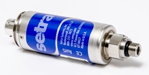 AccuSense Model ASM
A high performance pressure transducer such as the AccuSense Model ASM is required because of its ability to measure accurately in rugged conditions. It can withstand mechanical shock and vibration, thermal shock, corrosion, and other extremes found in harsh testing environments of dynamometers. Another advantage is its flexibility.
Versatility is typically required in the pressure ranges that customers are sensing. Setra can customize the Model ASM to meet key specifications because the engine tester often requires uncommon ranges. The AccuSense Model ASM pressure transducer has a large number of standard pressure ranges and can also customize ranges to accommodate any unique pressures a customer may have. The capacitive design of the AccuSense Model ASM allows for simple modifications to meet customer specifications with fast delivery time.
